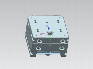
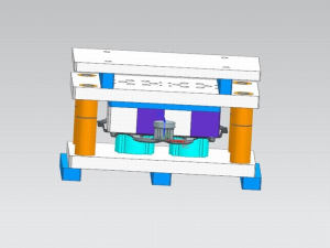
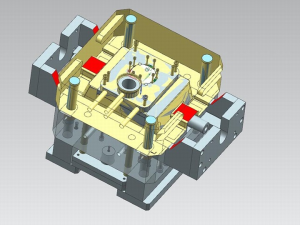
The structural design of the stamping and trimming die is equally important as the process design, and the influence of the trimming process design should be considered. The structural design of the trimming die considers strength, direction, positioning, assembly and other points.
1. Mold structure strength design
The structural strength design of the mold involves many aspects such as safety, quality, efficiency, etc. The thickness and quality of each structural casting of the mold directly affect the strength of the mold. Figure 7 and Table 5 are the reference standards for the thickness of each structural casting of the trimming mold. Except for the above castings Except that the thickness should meet the requirements, other structures with insufficient strength should not appear in the design, and should be checked during the review of the mold structure design.
2. Segmentation and structural design of cutting edge blades
The upper and lower die-cutting blocks of the trimming die, the scrap knife, and the pressing plate constitute the main working parts of the trimming die. From the design considerations of operability and maintainability, the cutting edge is generally divided into multiple insert structures. For the insert part, please refer to Figure 8. On a flat surface, the cutting settings for the cut material are targeted to form a 90-degree angle with the trim line, with a tolerance of ±10 degrees (ie, 80 degrees 100 degrees). In cross-section, the cutting edge is 90 degrees from the cutting edge , the tolerance is ±20 degrees (ie 70 degrees to 110 degrees), as shown in Figure 9. If the cutting block does not meet the above conditions, the stamping parts are prone to burrs and other defects. In order to reduce the cutting force, the edge of the cutting die And the parts of the special-shaped punch are usually designed to be wavy.
3 Design of the pressure plate
The trimming template is used to blank the part during trimming, and the design of its stroke and blanking surface is very important. Before the upper die cutting edge contacts the part, the pressure plate should ensure a minimum pre-compression of 10mm. The amount of pre-compression, cutting amount and maximum cutting The amount of cutting edge together determines the stroke of the blanking plate. When the thickness of the workpiece is less than 1mm, according to experience, the stroke of the platen is generally set to 30mm. When the sum of the three parameters is greater than 30mm, set according to the calculated value. Trimming with wedges When the mold is working, it is necessary to verify the synchronization of the wedge, the pressure plate and the guide, and draw the stroke diagram to ensure that it meets the technical requirements. In order to reduce the cost of mold manufacturing, the gap design of the trimming lower mold and the blanking plate structure is carried out. However, its effective working surface should be guaranteed. The reference position and range of the open space are as follows: Trimming: the distance between the lower die and the trimming line is 4050mm, and the distance between the pressing plate and the trimming line is 30mm. 20mm from the punching outline.
4 Scrap Knife Construction and Setup
The processing of trimming die waste is directly related to production efficiency. In actual production, the production line downtime caused by the waste of trimming die cards accounts for a considerable proportion. Figure 10 is a schematic diagram of the structure of the scrap knife and the amount of cutting edges. When the thickness of the workpiece is greater than When it is 1.2mm, the back support structure should be set up behind the scrap knife, and the angle of the back support structure should be consistent with the inclination of the knife back. Second. Figure 11 is a schematic diagram of the structure of the second cutting of scrap. When setting the second cutting of scrap, because the scrap is free to cut, it is easy to fly out of the mold, and a scrap protection plate must be installed.
5 Scrap chute and scrap box The design scrap of the trimming mold is usually handled by sliding out the machine or setting up a special scrap box. To ensure that the trimming scrap can slide out of the worktable freely, the scrap chute should meet the following requirements:
(1) Fully ensure the opening size of the trimmed waste skateboard slideway, and the skateboard tray is placed on the upper end of the skateboard.
(2) When the slideway is too long, two folding slideways should be set.
(3) Under normal circumstances, the inclination angle of the scrap chute should not be less than 25 degrees, and the inclination angle of the secondary scrap chute should not be less than 20 degrees. Steel, rollers and other measures to make the garbage slide out smoothly. If necessary, a vibrating skateboard can be used.
(4) When arranging the trimming scrap slides, the structural strength of the surrounding mold castings should be guaranteed, and the necessary height with the mold clamps should be ensured so as not to interfere with the installation of the mold clamps. Usually, the scrap box is used to store stamping scraps. Set punching scraps When removing the waste box, its work efficiency and ergonomics should be fully considered, and the shape and arrangement position of the waste box mechanism should be optimized.
Various factors should be considered in combination with the actual situation. The trimming and punching quality of stamping and trimming dies are produced and designed. The optimized trimming process design and die design not only determine the trimming quality, manufacturing cost, Production efficiency, etc., and it is very helpful to formulate solutions to trimming defects.


